1 Introduction
1.1 Document Overview
The purpose of this document is to outline the main Network infrastructure high-level design (HLD) for the Rubin Observatory summit and base sites. It would recommend an architecture based on the requirements set by the project, especially -but not limited to- the Tiger Team in different ICDs and in the documents mentioned in section 1.4.
The intent of this document is to provide an architecture that fulfills the requirements outlined by the project, keeping in mind current needs but also future growth of the network. The HLD does not delve into low-level details (i.e. configuration files, performance analysis, etc…).
As long as the HLD status is draft, it is susceptible to modifications and additions by the IT group or by the request of other subsystems.
After acceptance this document may or not be under change control, and regardless of that this is considered a living document that will be updated upon requirement addition or changes, experiences in the deployment, and operations process.
1.2 Scope
- Fulfill the current Network Infrastructure needs of the project and allow for future growth.
- This document focuses only on INTERNAL Network Infrastructure in Chile, it does not cover any Long-Haul Networking (LHN) design beyond the interfaces that connect the internal network in Chile to such system. For information about the LHN design please refer to the latest release of LSE-78.
- While this document mentions firewalls from a functional perspective, it DOES NOT contain specific cybersecurity approaches and neither the firewall hardware.
- This document DOES NOT cover requirements for services such as Wi-Fi and VoIP beyond the interfaces that connect the internal network in Chile to such systems. For information about the aforementioned services please refer to the following documents:
- This document DOES NOT cover requirements for Network Infrastructure integration with other AURA projects.
1.3 Assumptions and Caveats
- It is assumed all the project concepts derived from other documents such as those mentioned in section 1.4 and/or the associated ICDs, are correct and remain unchanged.
- It is assumed the reader is familiar with the project Network Infrastructure requirements for Chile. Furthermore, it is also assumed the reader is familiar with Networking technologies such as routers, switches, firewalls, and protocols such as BGP, EVPN, VXLAN, IS-IS, OSPF, etc…
- Even if specific networking solutions and vendors are mentioned in this document, the topological design will be neutral and vendor agnostic. The only exception to this point will be if any of the chosen networking solutions have a requirement that demands a specific topology and will be mentioned as an option. The final topology will be described in the Low-Level Design (LLD) version of this document.
2 Technical Solution Overview
2.1 Data Gathering
Rubin Observatory in Chile from the beginning of the project did rely on the network infrastructure provided by CTIO CISS to provide internet access to its early users, most of them transitioning from other projects such as SOAR, CTIO, and Gemini, therefore the first development services, for instance, were hosted in CISS’s provided networks and servers, which were slowly transitioned to Rubin Observatory’s own network infrastructure during the 2015-2017 period, while still very basic and focused just on internet access plus access to some internal resources. The project services such as websites and archive services have always been hosted in Tucson and access to them is over commodity internet without the need for a VPN connection. Early in 2017, as more staff transitioned from Tucson to La Serena and new local staff was being hired, the Rubin Observatory IT North group implemented the first transition network in La Serena, still hosted at the CISS computer room inside the old NOAO south building, and still using the existing Ethernet infrastructure to reach with physical links to the Rubin Observatory offices, but now providing a different network segment and intranet access to more services hosted in Tucson over a site-to-site IPsec VPN, plus an independent link to the Aura Border Router to reach commodity internet without crossing CISS’s internal networks. The only exception in this first transition network was the VoIP infrastructure which still relied on CISS.
From this point and on, the Chilean Rubin Observatory networks slowly started to scale with local services such as Active Directory and Exchange, plus archiving for webcams at the construction site. In July 2017 Rubin Observatory decided to procure the first batch of network hardware to become fully independent in terms of network infrastructure during the upcoming years, which required the construction of the new summit and base sites to be finished before this to happen completely.
As the Rubin Observatory summit telescope building and the new base facilities are ready, the following summary requirements must be fulfilled by the new Network Infrastructure:
- The architecture shall provide design modularity as different modules of the network will be implemented in different stages due to the nature of the construction phases, out of which the summit has the highest priority.
- The “solution” is defined as a group of technologies, vendors, and hardware chosen to implement the design defined by the Network Architect. The meaning of solution in this document in particular must not refer to a specific product model, as the whole network infrastructure is not implemented by a homogeneous technology stack.
- The solution must be able to provide wired connectivity to all the areas requiring it as defined in the different ICDs of the subsystems, either via UTP or Fiber Optic ethernet connections. Wi-Fi connectivity is covered in a separate High-Level Design (document).
- The solution must be able to provide Value-Added Services (VAS) which in case of the network infrastructure translate to services such as Power-over-Ethernet (PoE), Authentication, Authorization and Accounting, traffic filtering and access control, traffic prioritization through Quality of Service (QoS) techniques, monitoring and configuration programmability for eventual integration with software pipelines, etc…
- The solution shall provide support for standard protocols such as LLDP, OSPF, BGP, STP, etc… as the topological design will be agnostic and vendor-neutral even if part or the totality of the solution is proprietary. This is key to play along with a modular design where parts of the network can be replaced by another model or vendor hardware in case of contingency or due to specific requirements. The solution must also be able to provide full dual-stack IPv4/IPv6 support for its core routing protocols.
- The solution shall provide methods for redundancy and/or high-availability of the control, management, and data plane where needed.
- The solution must provide modularity and scalability options for its hardware and software, making possible horizontal and vertical scalability in key devices such as core or spine switches while providing cost savings through a pay-as-you-grow hardware approach. In terms of bandwidth, the solution must be able to scale using transceivers ranging from 1G to 10G in most devices, and 10G to 100G in key devices such as core and spine switches.
2.2 Chosen solution
The decision rationale was a technical analysis of the project requirements by several vendors and distributors held in the 2015/2016 timeframe by the Tiger Team, out of which Cisco Systems was the chosen vendor for most of the LAN, Datacenter, Wi-Fi and VoIP infrastructure. This document will only focus on the LAN and Datacenter infrastructure which build up the backbone of the main network that will connect systems and end-users together. Due to the extensive nature of the solution, containing a very diverse group of devices, the list will be broken up by functional blocks.
2.2.1 Campus Network Hardware
The campus network is a functional block that contains switches where end-users and systems such as IP phones, laptops, printers, Access Point, connect to the network. More detail is provided in section 3.2.
Distribution Switches
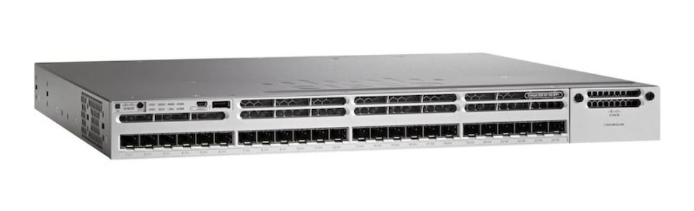
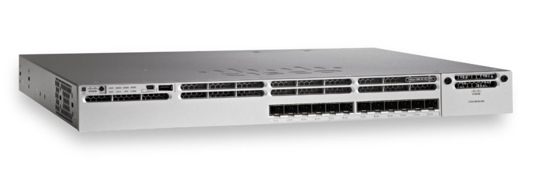
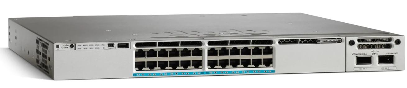
- Cisco Catalyst C3850-12XS and 24XS: Distribution switches whose function is to aggregate the access switches to be installed in the technical rooms all around the buildings, using a 12 port SFP+ version for the base datacenter and a 24 port SFP+ version for the summit. Both models are expanded in capability with a C3850-NM-4-10G module for 4 additional 10G SFP+ ports.
Access Switches
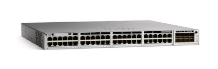
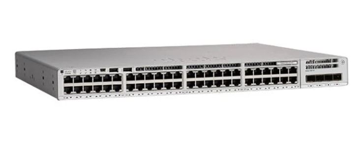
- Cisco Catalyst C9300-48UXM-E: Access switches for the summit control room areas, providing 48 1G/2.5GBASE-T ports from which the last 12 are also mGig (1G/2.5G/5G/10G), all ports also providing universal PoE (UPOE). This model is expanded with a C9300-NM-8X module for additional 8 10G SFP+ ports used mainly for uplinks to distribution switches.
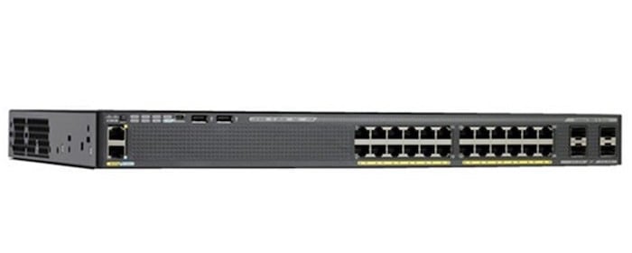
- Cisco Catalyst C2960X-24PD-L: Access switches for the summit site in minor office areas such as the electronics lab and the coating chamber office, providing 24 1000BASE-T PoE+ ports, plus 4 onboard 10G SFP+ plus ports used for uplinks to distribution switches.
- Cisco Catalyst C9200-48P-E: Access switches for the base site both datacenter offices and new building offices (NOB), providing 48 1000BASE-T PoE+ ports. This model is expanded with a C9200-NM-4X module for additional 4 10G SFP+ ports used for uplinks to distribution switches.
2.2.2 Core Network Hardware
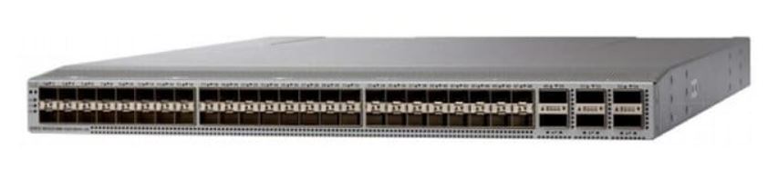
- Cisco Nexus C93180YC-EX: Datacenter class switch used for core routing in NX-OS mode, interconnecting the different blocks of the network (campus and control) plus access to other sites, all in layer 3, providing 48 10G/25G SFP+ ports plus 6 100G QSFP28 ports for key connections between sites.
2.2.3 Control Network Hardware
The control network is a functional block that contains switches where servers, custom systems, and control hardware such as IP sensors, PLCs, SCADA units, etc… are connected. More detail is provided in section 3.2
Part of the control network contains what is known as the data center layer, which is a group of high-speed state of the art switches with line-rate switching capabilities sitting inside the data center, connecting servers together for what is known as east-west traffic, and providing services from these devices to users in the campus network or at other sites, for what is known as north-south traffic. Rubin Observatory via the Tiger Team decided to move forward with proprietary software-defined networking (SDN) solution for this part of the network named Cisco ACI, which comes from Application Centric Infrastructure.
On a high-level, Cisco ACI is a solution that centralizes the control plane from all the switches in the data center (connected in a standard CLOS topology) into a controller known as APIC (Application Policy Infrastructure Controller), where an additional software abstraction layer orchestrates and automates the protocols which are part of the solution, mainly VXLAN for the data plane (also referred as overlay) and IS-IS for the routed topology used by VXLAN (also referred as underlay). MP-BGP is used to exchange routes between each switch in the topology; a REST API to integrate ACI into software pipelines is also provided by the controller. Any configuration changes to the data center network (i.e. Cisco ACI switches) are done in the APIC controllers, either via its graphical interface or via the REST API.
VXLAN can be extended to other sites using MP-BGP and EVPN following vendor-specific setups, one of them being “multi-pod”, which will be covered in section 3.2 as an option to extend layer 2 networks between sites. Cisco ACI is a topic on its own, please refer to the official ACI documentation repository
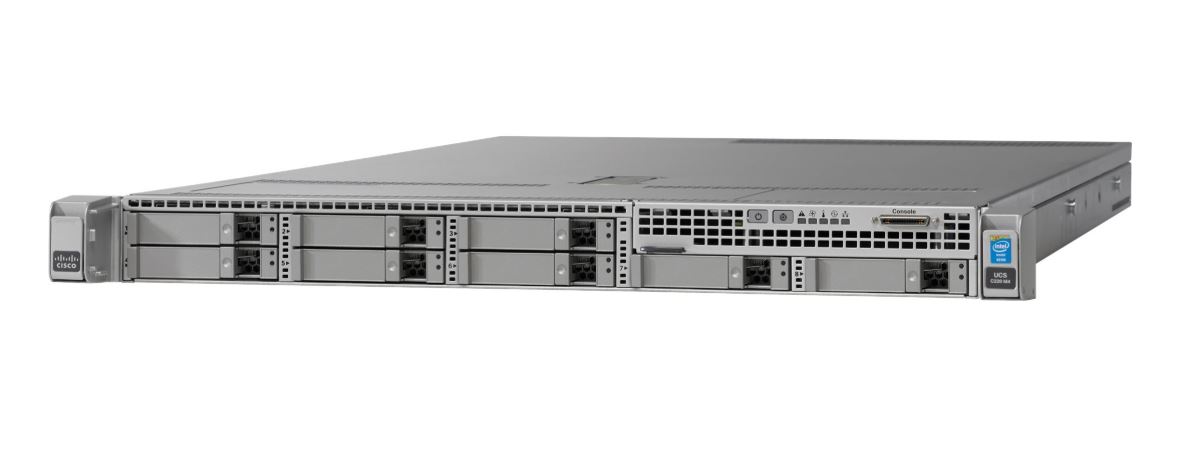
APIC Controllers APIC-SERVER-L2: As mentioned before, the APIC controllers are servers running the Cisco ACI software that implements the control plane for all the datacenter switches and plus the REST API. These controllers are based on Cisco’s UCS M220 M4 servers, 3 for the summit, and currently only 1 for the base site, a situation that may change in the future depending on the scalability plans of the project and if a multi-pod setup is implemented between the summit and base sites. Please refer to section 3.2 for more information on multi-pod.
Spine Switches
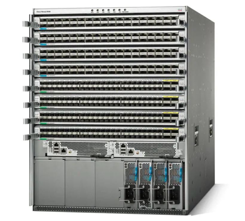
- Cisco Nexus C9504-B3-E: Modular spine switch running in ACI mode deployed as a pair in the summit computer room, with 4 slots for line cards and a baseline of 1 N9K-X9732C-EX card providing 32 100G QSFP28 ports to connect the leaf switches together in a CLOS topology.
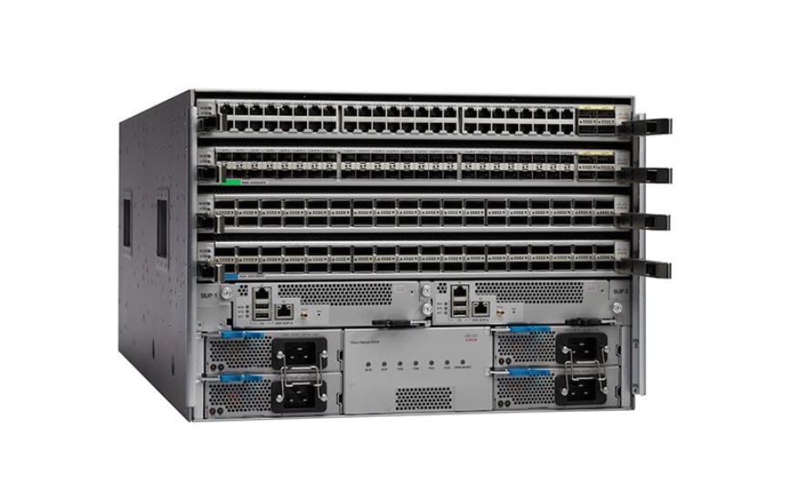
- Cisco Nexus N9K-C9508-B3-E: Modular spine switch running in ACI mode deployed as a pair in the base data center, with 8 slots for line cards and a baseline of 1 N9K-X9732C-EX card providing 32 100G QSFP28 ports to connect the leaf switches together in a CLOS topology.
Leaf switches
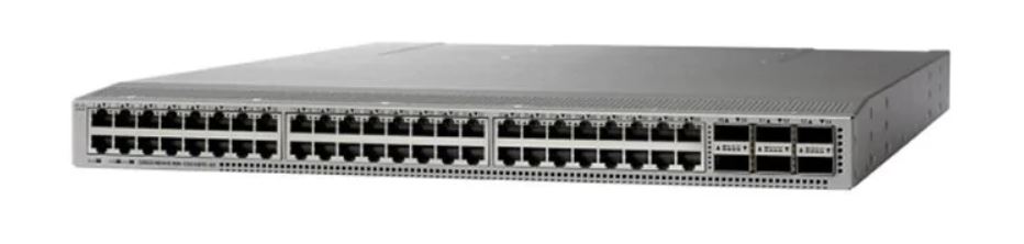
- Cisco Nexus C93108TC-EX: Fixed leaf switch running in ACI mode both at the summit computer room and base data centers, with 48 1/10GBASE-T ports plus 6 100G QSFP28 ports for uplinks to the spine switches.
- Cisco Nexus C93180YC-EX: Fixed leaf switch running in ACI mode both at the summit computer room and base datacenters, providing 48 10G/25G SFP+ ports plus 6 100G QSFP28 ports for uplinks to the spine switches and other key connections. These switches have a special function: being a border leaf, which is basically the leaf switch that aggregates the connections coming in and out the CLOS topology (also known as Fabric, or ACI Fabric in this case), which can be either layer 3 (routed) or layer 2 (802.1q or untagged access VLANs). The border leafs are the ones connecting to the core switches in layer 3, and matching VLAN tags coming from other switches via trunk links such as the campus distribution switches and the extended leaf switches. For more detail on the topology of the control network please refer to section 3.2.
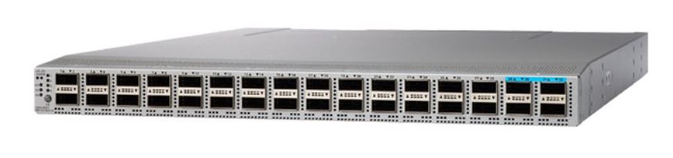
- Cisco Nexus C93180LC-EX: Fixed leaf switch running in ACI mode only at the base datacenter, requested specially to cover the needs of a 100G storage unit for the base site by NCSA. This switch provides 32 40/50G QSFP+ ports as a baseline or can also be reconfigured to provide only 18 100G QSFP28 ports.
Extended Leaf switches
These switches are basically regular access switches but the denomination “extended leaf switches” is used to reflect the fact that these serve as a functional L2 extension of the ACI Fabric being directly connected to the border leafs via redundant and aggregated LACP 802.1q links.
The use-case for non-ACI switch to extend the ACI topology directly in L2 is that some industrial areas require expedited control network access but space is constrained for a Nexus switch to fit in and for functions such as out-of-band (OOB) access where an ACI switch would be certainly overkill.
- Cisco Catalyst C9300-48UXM-E: Extended leaf switch for indoor areas outside the summit computer room where control network access is needed, providing 48 1G/2.5GBASE-T ports from which the last 12 are also mGig (1G/2.5G/5G/10G), all ports also providing universal PoE (UPOE). This model is expanded with a C9300-NM-8X module for additional 8 10G SFP+ ports used for uplinks to border leafs. This particular model is the same as the campus access switches used in the control room, and in the control network, its use is only foreseen at the Auxiliary Telescope.
- Cisco Catalyst C3850-24XU: Extended leaf switch for indoor areas outside the summit computer room where control network access is needed, providing 24 mGig (1G/2.5G/5G/10G) ports with universal PoE (UPOE). This model is expanded with a C3850-NM-2-10G module for additional 2 10G SFP+ ports used for uplinks to the border leafs.
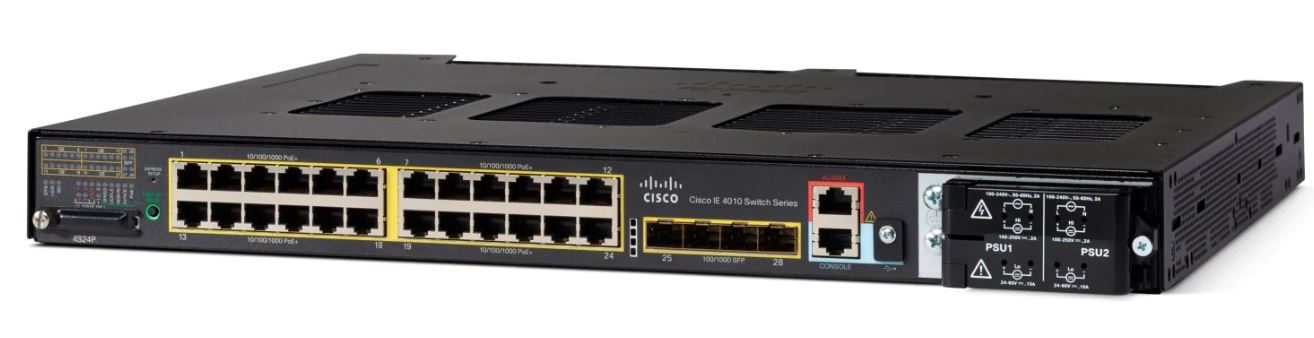
- Cisco IE-4010-4S24P: Extended leaf switch for outdoor industrial uses outside the summit computer room where control network access is needed, providing 24 1000BASE-T PoE ports plus 4 onboard 1G SFP ports for uplinks to the border leafs. This particular model is foreseen to be used in all the control cabinets of the Telescope Mount Assembly (TMA) plus other outdoor cabinets such as the calibration hill DIMM tower.
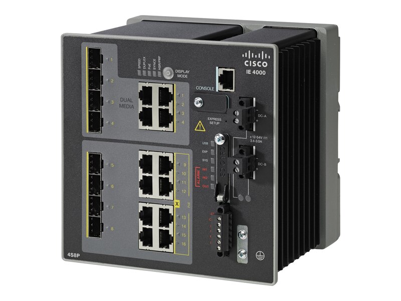
- Cisco IE-4000-4GC4GP4G-E: Extended leaf switch for outdoor industrial uses outside the summit computer room where control network access is needed, providing 12 ports with a distribution of 4 combos 1000BASE-T or 1G SFP ports for uplinks to the border leafs, 4 fixed 1000BASE-T and 4 1000BASE-T with PoE. This particular model is foreseen to be used in small outdoor cabinets such as the calibration hill Weather Tower, All-Sky Camera cabinet, and the main generator hut.
- Cisco Catalyst C2960X-24TS-L: Extended leaf switch for out-of-band (OOB) uses inside the summit computer room, providing 24 1000BASE-T ports plus 4 onboard 1G SFP ports for uplinks to the border leafs.
- Cisco Catalyst C9200L-48T-4G-E: Extended leaf switch for out-of-band (OOB) uses inside the base datacenter, providing 48 1000BASE-T ports plus 2 onboard 1G SFP ports for uplinks to the border leafs.
3 Proposed Network Architecture
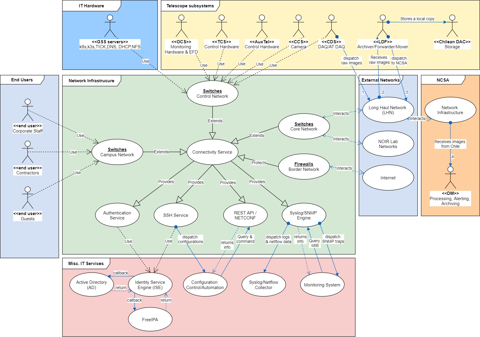
3.1 Logical Design
3.2 Physical Design
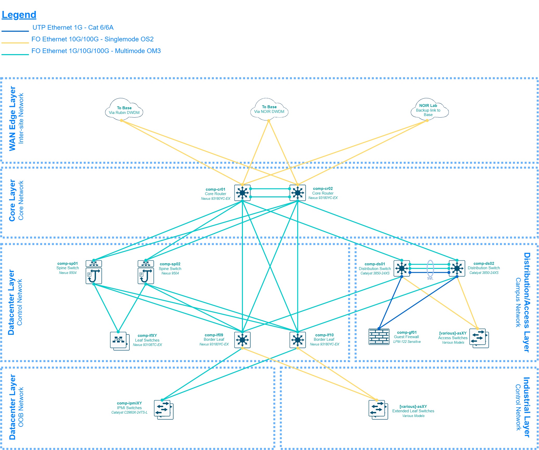
3.2.1 Base Site - La Serena

The design shown in the diagram above represents the overall project network at the base site, which paradoxically will be the last part of the network to be implemented due to timing differences between the summit and base site construction phases and resource availability, therefore several stages of “transition topologies or networks” are expected during the 2018 to 2020 period.
The design will be described up-down, starting at the border of the project’s network which is the AURA Border Router. This router is what AURA and the NOIR Lab IT group (ex-CISS) call “the backbone” of the Chilean AURA network, as it aggregates the traffic from all the AURA managed projects before routing to the commodity internet links, and educational networks. Rubin Observatory will rely on the Aura Border Router for the announcement of our IP prefixes via BGP on the AS19226, currently summarized and announced as 139.229.0.0/16. Rubin Observatory has assigned a good portion of that space as specified in LSE-449, and the AURA Border Router shall be able to determine which network is available behind which device when routing towards Rubin Observatory, either via static or dynamic routing; that specific configuration is outside the scope of the Rubin Observatory IT group.
The first layer of the Rubin Observatory network in Chile is the Internet Edge, also known as the Border Network, where a group of 3 redundant firewalls is connected to the AURA Border Router doing default routing towards the SVIs provided by NOIR Lab for extranet access, which as mentioned before may be static or dynamic depending on the configuration applied by the aforementioned group. This layer groups all the security devices protecting the internal network in different stages and setups, which are not openly discussed in this document as its sensitive information following LPM-122, but on a high-level there’s a firewall cluster to aggregate remote access VPN connections, connecting to an internal VPN DMZ segment for additional security enforcements, then there’s a guest firewall cluster to provide internet access to guests and contractors visiting our sites, monitoring their activity and preventing access to the intranet, and finally there’s a main border firewall cluster which aggregates all the traffic coming in and out the internal networks in Chile, implementing our main security policies using several features, which are sensitive and outside the scope of this document; this is the main entry point for internal networked resources.
These firewalls are aggregated in separate segments and VRFs -depending on the nature of its traffic- on a pair of leaf switches (also referred as “border leafs”) corresponding to the datacenter layer discussed later, but it’s important to mention that these switches are multi-functional and key in the design, as they not only provide the links towards the Internet Edge but also interconnect the 3 major internal blocks of the Chilean intranet: the Datacenter, Core and Campus layers.
The Datacenter Layer, also known as the Control Network, is where all the compute hardware is connected, mainly servers, storage units, custom hardware for the different project sub-systems, etc… this layer, as briefly mentioned in section 2.2.3 will be implemented using Cisco Nexus switches in ACI mode on a CLOS topology (also referred as ACI fabric), providing a VXLAN overlay with MP-BGP doing the routing for the different VRFs. The underlay is completely routed and each leaf switch provides a local anycast gateway for every bridge-domain defined network. The traffic exits the ACI fabric through the border leafs. The fabric filters traffic between networks using the concept of “contracts”, which is analogous to a stateless firewall but with the added benefit of being implemented in hardware, therefore filtering at line-rate speeds. There’s also a small component inside this layer, the out-of-band network (OOB), which uses the border leafs due to port density convenience to aggregate a group of non-ACI switches connected to the management ports (ipmi, cimc, idrac, etc…) of the networked devices within the site; while contained inside the Datacenter Layer and thus considered part of the Control Network, “OOB network” is explicitly stated as it has a different set of security policies, and also a failover network breakout additional to the border leafs; this information is considered sensitive and outside the scope of this document. Please note there are a couple of direct links between the spine switches and the core routers, these are optional 100G links for an ACI-specific setup called “multi-pod”, which is addressed in section 3.2.3. On a side note, you will notice the ACI fabric uses multi-mode OM4 links in the base site, this is because by the time we configured the bill of materials, the 100G BiDi QSFP were already available, and since it uses a regular LC connector instead of MTP-12 it helped to lower down the fiber cabling costs. The summit site bill of materials considered direct attachment QSFP28 cables but in the future, those may be migrated to 100G BiDI QSFP as well.
The Core Layer, also known as the Core Network, is the backbone of the local site, it will span to the summit as well using the dark-fiber DWDM circuits implemented as part of the LSE-78 plan. These are 2 Nexus switches running in NX-OS mode doing pure layer 3 routing using BGP towards the Datacenter Layer and the Long-Haul Network (LHN), and OSPF towards the Campus Network and partially to the Internet Edge layer. This network is where a backup link to the summit via the NOIR Lab network infrastructure will connect, once technical details are sorted out as it will probably be a hybrid fiber/copper/microwave solution.
The Distribution/Access layer, also known as the Campus Network, is the aggregation layer for all the feature-rich access switches providing services to end-users: laptops, desktops, printers, IP phones, access points, etc… The campus Networks are defined in the distribution switches and announced to the core using OSPF, all routing between these networks occur in the distribution switches, the access switches are only used as layer 2 bridges even if they have layer 3 capabilities, no proxy-arp is implemented nor needed at this level.
The WAN Edge, also known as the Inter-Site Network, is the layer where are the links going to the summit, NOIR Lab, and NCSA are present, most (if not all) of them are directly connected to the Core Network. This layer interacts directly with the Rubin Observatory DWDM, to get a pair of 100G links to the summit for connecting the core routers at each site together for an optional ACI “multi-pod” setup. It also interacts with the NOIR Lab DWDM to get a pair of 10G links to the summit for the same purpose but for general traffic routing (both control and campus) via an alternative physical route (i.e. the Pachon’s communication caseta), and it does indirectly interact with REUNA’s DWDM via the Rubin Observatory Border Router, which will provide the 100G link via the Long-Haul Network (LHN) to NCSA for dedicated image data transfer. Please note there’s an optional firewall in the diagram for this connection, which is specified only if needed as the LHN BGP peering should be private, and considered secure in general terms. Additional measures will be implemented to secure this BGP peering as to not need a firewall there, given the challenges it brings due to the need for BGP support, SFP+ ports, and near-10G firewall throughput. Please also note that if such a firewall is implemented, its scope is only to filter the Control Network traffic crossing the LHN towards NCSA, as the forwarders will be directly connected to the Rubin Observatory Border Router. The details of the LHN setup are covered in LSE-78.
3.2.2 Summit Site - Cerro Pachon
The summit network design follows a very similar pattern to the base which is evident by looking at the diagrams, with major differences only on the upper layers of the design as firewalls are not broadly needed since the site depends on the base network for extranet access. Please note that the aliases to each layer (e.g. Core Network, Campus Network, Control Network, etc…) are also valid for the summit and used interchangeably with its associated layer name, also due to this fact and having described the layers in detail on section 3.2.1, the descriptions for each network in this section will be kept to a minimum.
The first layer of the summit network is the WAN Edge which receives all the links coming from the base network and eventually from NOIR Lab networks, directly into the core switches. The Core Layer is tightly coupled to the WAN Edge as it implements it entirely in this case, and just like at the base site, it is composed of 2 Nexus switches in NX-OS mode doing purely layer 3 routing with BGP towards the WAN Edge and the Control Network, and OSPF to the Campus Network.
The Distribution/Access Layer or Campus Network is an exact match to its base site counterpart with differences in switch models and implementing a firewall to filter local guest networks.
The Datacenter Layer or Control Network is as well an exact match to its base site counterpart with differences in switch models but always keeping Cisco ACI as the core technology behind the fabric implementation. The Control Network has an out-of-band (OOB) non-ACI layer 2 extension just like at the base known as the OOB network, but it also contains an additional non-ACI layer 2 extension which is a direct extension of the Control Network in terms of policies (unlike the OOB network) and therefore referred by such name; in the diagram, it is shown as Industrial Layer, due to the presence of mostly industrial-rated switches which will be implemented outdoors or in heavy industrial areas such as the level 1 utility area, the level 3 integration area, and levels 5 to 7, including all the switches inside the cabinets of the Telescope Mount Assembly (TMA).
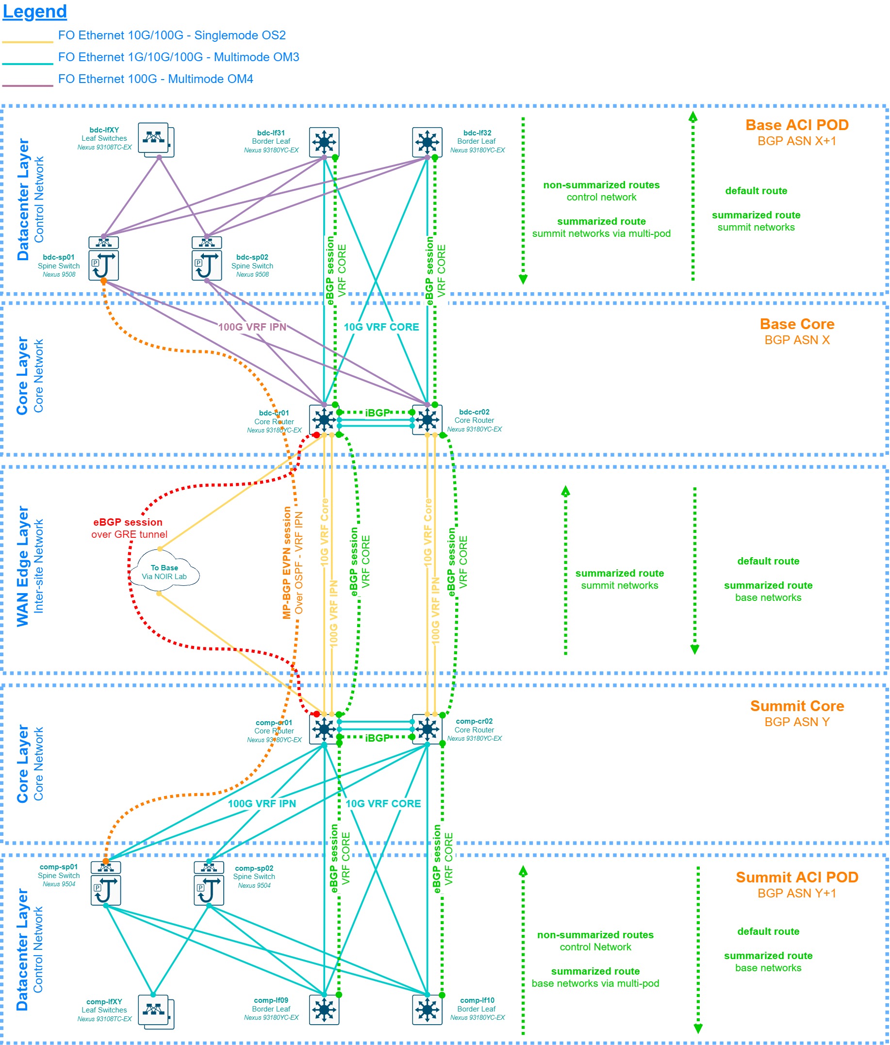
3.2.3 Summit to Base WAN - Layer 3
The diagram below, while still very high-level, provides insights as to how the layer 3 layout between the summit and base sites should look like by the commissioning period. The core switches are directly connected to each other with 10G/100G links and using BGP to share routes, each site having its own private Autonomous System Number (ASN). The low-level design should be rather simple and avoid unnecessary routing clutter. There’s a backup link that may be provided by NOIR Lab using its microwave links between Cerro Pachon and Tololo, to La Serena. The design should consider what NOIR lab can provide for this implementation, which can range from a spanned VLAN between the sites to a dedicated or shared VRF. Considering the lack of technical details for such link at the time of this writing, we will consider the simplest option which is a shared VRF at each site with a loan IP address from NOIR Lab’s IP range, and the implementation of a GRE tunnel to cross their network to avoid routing complications, and also to allow us to modify the BGP metric to learn routes through this tunnel as a backup. Given the limited availability of network infrastructure and fiber optic links between the Summit’s computer room and NOIR Lab’s closest network distribution point (Pachon’s communication caseta), the baseline is a single link connecting the first core switch at each site together.
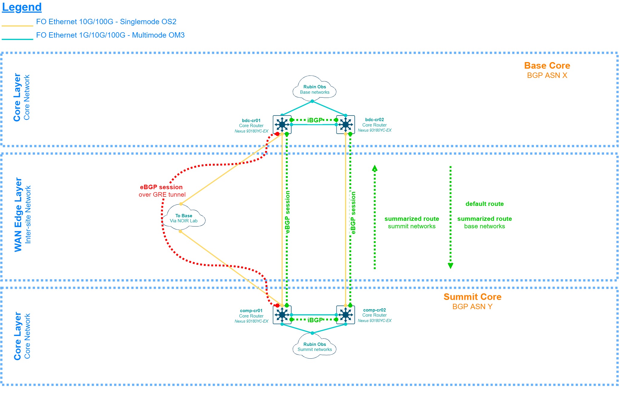
The diagram discussed above is agnostic in terms of design, however, the chosen solution to implement the Datacenter Layer (Cisco ACI) provides the option of an MP-BGP/EVPN control plane extension between the sites called “Multi-pod”. This allows for the data plane (VXLAN) to be extended between the sites as well, which translates to Layer 2 adjacency for end-devices connected to the same bridge domain. This setup has several technical requirements, mainly a pair of routers or Layer 3 switches at each site with OSPF reachability and multicast bidirectional support, plus a physical connection between these devices with maximum 50 milliseconds of RTT (round-trip time). The original proposal from the Cisco considered this setup as the baseline, however, this requires the DWDM units to provide dual 100G QSFP ports on a dedicated line card and wavelength, which by 2017 had an unknown estimated time of delivery by the DWDM vendor, therefore this design is presented as an option instead of a baseline.
3.2.4 Summit to Base WAN - Optical (DWDM)
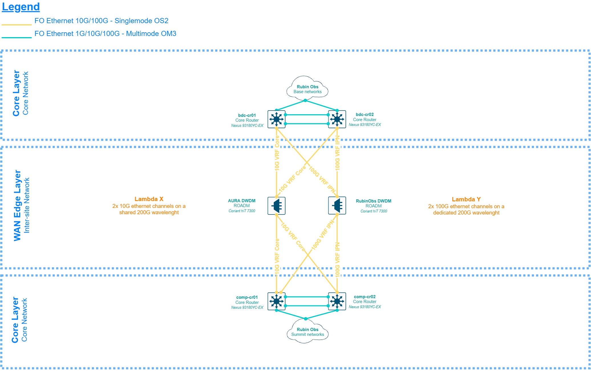
The diagram above provides a brief description of the optical layer implemented by the DWDM units for the inter-site connectivity. This is subject to changes and presented only as a reference, the source of truth for this setup can be found in LSE-78.
3.3 Scalability
In the designs for each site, there are 2 major layers that provide the most port density both to users and systems, the Control and Campus Networks. These are Distribution/Access Layers and horizontal scalability is achieved by adding additional access/leaf switches, therefore the only limitation is the number of uplink ports available at the spine and distribution switches respectively. For the Control Network, the solution is modular therefore 2 spines with 1 100G line card are good enough for the construction period, but this can scale up to 4 of those in each chassis for a maximum of 128 100G ports. For the Campus Network, the solution is fixed therefore the maximum amount of access switches is 24 for the summit and 12 for the base. The aforementioned scalability numbers are considered sufficient to provide connectivity to all the baseline areas in the observatory design.
In the case horizontal scalability is not enough, vertical scalability is feasible in both layers, adding Fabric Extenders to the leaf switches in the Control Network, and implementing stacking in the Campus Network (StackWise). The Control Network also scales vertically at the Border Leafs when connecting the non-ACI switches for layer 2 network extensions outside the Fabric. The Core and the WAN Edge Layers are can only scale horizontally if additional downlinks or Distribution/Access Layers are needed, up to the maximum available ports in each switch, however, this is not foreseen as the Core Layer, and mainly the WAN Edge is physically limited by the fiber circuits, ports and wavelengths available at each DWDM unit, especially for the 100G links which require special QSFP28 line cards and transceivers.
3.4 Design Considerations
- Rubin Observatory scope is limited to the implementation of the internal networks and fiber circuits at each site, but the WAN and extranet infrastructure is provided by NOIR Lab, this includes the internet access via the AURA Border Router and the DWDM units at each site, which are managed and monitored by REUNA as a partner and service provider to AURA.
- The use of private BGP ASNs is necessary and the AS will be stripped off if necessary when peering with other groups or organizations.
- Only Rubin Observatory’s IT group and NOIR Lab are authorized to announce the observatory specific prefixes in the 139.229.0.0/16 range. Several internal groups will be assigned with subnets from such range, however, the advertisement of those subnets by any other AS not 19226 to the public internet table while not being explicitly authorized by Rubin Observatory/NOIR Lab is strictly prohibited and considered a criminal act.
- As stated in LSE-449, the use of RFC 1918 IP addresses and several other private addressing ranges will be common, however, we must NOT announce bogon networks to any public BGP peers.
- Complex but simple is good, complex but complicated is not. Any routing or switching configuration must be kept as simple as possible while covering all the observatory needs. Routing tables must be kept as small as possible and route summarization/filtering is expected whenever feasible and advisable.
- The use of NAT is only for specific purposes and/or of the last resource and should not be used as a security mechanism to protect private networks. The use of UPnP-enabled devices is prohibited unless explicitly authorized, and only if UPnP can be completely disabled.
- Port forwarding is a contingency mechanism and should not be considered common practice. If port forwarding is needed it may imply a network issue to be solved. Port forwarding is restricted, only allowed in emergency scenarios or where strictly necessary.
- While the network infrastructure is required to be dual-stack IPv4/IPv6 ready, during the construction phase efforts will be centered in IPv4. IPv6 may be implemented in the future if there’s a use case and if NOIR Lab provides Rubin Observatory with the necessary routable IPv6 segments. Some devices such as Windows systems use 6-to-4 tunnels natively if available, which is acceptable as such traffic is seen as IPv4 by the network infrastructure.
- Standard protocols must be used whenever feasible and advisable. The use of proprietary or partially open protocols such as EIGRP should be avoided.
- Unless limited by the hardware the links between the network devices should be 10G whenever feasible. The current price difference between single-mode and multi-mode links is negligible for most of the implementations, therefore multi-mode fiber should be used when required by the system and mostly inside the datacenter/computer room. Links to the outside of those rooms should be single-mode whenever possible to future-proof the link bandwidth scalability.
- Equal-cost multipath (ECMP) routing must be implemented whenever possible but taking care to do proper traffic balancing. Per-packet load balancing over links with different bandwidth and/or jitter/latency parameters is not advisable as it may bring out-of-order packet issues. Cisco CEF must be disabled in some links to allow proper load balancing.
- The routing and switching protocols to be implemented shall be configured beyond its default parameters to allow sub-second convergence upon hardware or link failures.
- Modeling the network low-level design before implementation and/or major changes are recommended if technically feasible. Physical models are preferred but virtual models are acceptable if the operative system of the network devices can be fully emulated, at least for the protocols being implemented.
3.5 Redundancy and High-Availability
Redundancy is foreseen for most of the network infrastructure, especially at the summit site where several mission-critical systems are present. Access layer redundancy is achieved by connecting the end-devices to a pair of access/leaf switches in an active/standby or in an LACP active/active setup. Special care should be taken when using LACP as drivers on the end-devices may behave differently (e.g. bonding vs teaming) than the network devices upon hardware or link failures. LACP option mismatches are also common, therefore testing is advisable before moving LACP configurations into production.
For most of the topology, both summit and base, network devices have their own control, management, and forwarding planes, however, Cisco ACI switches share a common control plane that lives in the APIC controller. High-availability is implemented by having APIC controller clusters, each cluster member having a shard copy of the DB; for single pod implementations 3 APIC controllers are the minimum advisable and for multi-pod implementations, it is 4, 3 at the main site and 1 at the second site. If the controllers are completely lost the control plane is lost as well but the ACI switches implement a local control logic which allows the packet forwarding to keep working, with the only limitation of not being able to implement configuration changes until part of the APIC cluster is recovered.
3.6 Security
The chosen solution supports a broad range of security mechanisms but not all of them will be implemented. The in-depth details of the security setup for the Rubin Observatory are sensitive and outside the scope of this document, however, these are the baseline requirements to be considered for a low-level design.
- AAA must be implemented for each network device using a NAC service such as Cisco ISE.
- The least-privilege principle must be considered when providing access to network devices. Administrator and system accounts shall only allow for the authorized commands to be run.
- SSH keys authentication is preferred and the replacement of public SSH keys must be observed carefully.
- If local passwords are needed these must be kept in a secure password management repository or system, with dual-factor authentication.
- End-devices must be authenticated with 802.1x whenever possible. Each site must provide enough redundancy and/or high-availability for the NAC service to allow authentication even if the site is isolated.
- Telnet and any other unencrypted management protocols are prohibited unless explicitly authorized and strictly necessary.
- Bandwidth restriction and storm control features are acceptable to avoid starving links, both internal and NOIR Lab provided.
- Blocking and/or restricting ports upon security violations is mandatory, plus triggering an immediate alert via a monitoring protocol or system to the IT group.
3.7 Monitoring
The SNMP protocol is the most common way to monitor network devices and is still the first and easiest option to implement monitoring along with ICMP. This service run queries to the devices using the Cisco-provided MIBs for hardware parameters such as CPU, RAM, and HDD load, plus additional parameters such as per-port load, environment variables such as inflow and internal temperatures, fan status, etc… depending on the level of granularity needed and agreed by the System Administrator in conjunction with the Network Engineer.
Logging is done via Syslog at debugging level to the local Syslog collector of the site and alerts may be configured for specific messages such as interfaces being down or flapping, hardware issues, etc… as a backup of the SNMP monitoring. Simple ICMP monitoring to the management interface of the devices is advisable, as it tends to be faster than SNMP or even Syslog to trigger an alert.
Custom bash or python scripts are also acceptable given the use-case, as well as the use of software abstraction layers that can query the units via SSH, special methods such as REST APIs or protocols such as NETCONF, to present that information to other services or databases.
3.8 Management
Several types of management methods are available for the chosen solution but the following must be implemented as the baseline:
- In-band management access to the devices must be based on TACACS+ provided by a NAC service such as Cisco ISE, synchronized with the local domain controller of the site, and implementing differentiated levels of access. For IT network administrators, the regular domain account shall provide read-only access and the admin domain account shall provide full access to the controller.
- Out-Of-Band (OOB) management is done via the service or management port, which is placed in a different and more protected network than in-band management.
- IPMI/BMC access is provided by the onboard Cisco CIMC hardware, also placed in a different and more protected network than in-band management. It may or not be in the same as the OOB management segment.
- A local administrator account is available for IT network administrators, but each device is configured to make use of it only in case of an emergency. No other local accounts must be present on the devices.
4 Appendix
4.1 Terminology and acronyms
| Term | Meaning |
|---|---|
| ACI | Application Centric Infrastructure |
| AD | Active Directory |
| API | Application Programming Interface |
| APIC | Application Policy Infrastructure Controller |
| ASN | Autonomous System Number |
| AURA | Associated Universities for Research in Astronomy |
| BGP | Border Gateway Protocol |
| BMC | Baseboard Management Controller |
| CEF | Cisco Express Forwarder |
| CIMC | Cisco Integrated Management Controller |
| CISS | Computing Information Services South |
| CLI | Command-line interface |
| CTIO | Cerro Tololo Inter-American Observatory |
| CLOS | Topology created by Charles CLOS |
| DB | Database |
| DWDM | Dense-Wavelength Division Multiplexing |
| EVPN | Ethernet Virtual Private Network |
| EIGRP | Enhanced Interior Gateway Routing Protocol |
| HA | High Availability |
| HDD | Hard-Drive Disk |
| HLD | High-Level Design |
| ICD | Interface Control Document |
| IEEE | Institute of Electrical and Electronics Engineers |
| IS-IS | Intermediate System to intermediate System |
| ISE | Identity Service Engine |
| IT | Information Technology |
| IPMI | Intelligent Platform Management Interface |
| LACP | Link Aggregation Protocol |
| LHN | Long Haul Network |
| LDAP | Lightweight Directory Access Protocol |
| LLD | Low-Level Design |
| LSST | Large Synoptic Survey Telescope |
| MIB | Management Information Base |
| NAT | Network Address Translation |
| NETCONF | Network Configuration Protocol |
| NIC | Network Interface Card |
| NOAO | National Optical Astronomy Observatory |
| OOB | Out of band |
| RADIUS | Remote Authentication Dial-In User Service |
| POE | Power Over Ethernet |
| OSPF | Open Shortest Path First |
| SFP | Small Form-Factor Pluggable |
| SNMP | Simple Network Management Protocol |
| SNR | Signal to noise ratio |
| SSH | Secure Shell |
| SSID | Service Set Identifier |
| TACACS | Terminal Access Controller Access Control System |
| VLAN | Virtual local area network |
| VXLAN | Virtual Extensible Local Area Network |